In QA we use robotic arm to autonomously operate a multifunctional device (MFD) according to a given test that is repetitive, time consuming or not performable by a human.
How does the robot know where is the screen located? How do the 2D screen coordinates transform to the robot’s system?
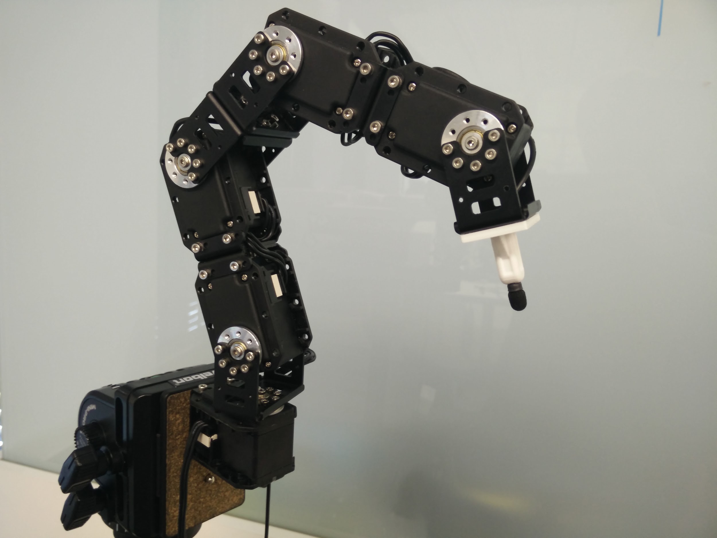 Robot moves the end effector (stylus) in the 3D Cartesian coordinate system with the origin [0,0,0] at the center of the first servomotor. Position of the stylus is then transformed to angles of all servomotors by inverse kinematics. It is also possible to calculate position of stylus given the angles of the servomotors (forward kinematics). However the screen of the MFD is a 2D plane in the 3D space with unknown origin, dimensions and rotations. Robot needs to know where the screen is located relatively to its origin in order to correctly tap any button on the screen.
Dimensions of the screen need to be measured by hand in millimeters. We use 2D coordinates with origin at the bottom left corner to define position on the screen. In 3D space position and rotation of any plane is uniquely determined by three non-collinear points. If these three points are known, transformation matrix can be found. This matrix multiplied by position on the plane is equal to corresponding position in 3D space.
Previously we used ‘basic’ calibration where the robot is navigated through the bottom left corner [0, 0] (origin of the screen), top left corner [0, height] and top right corner [width, height]. At each corner, stylus’ position (in 3D space) is saved and transformation matrix is calculated. This method of calibration requires a lot of precision because even a slight deviation from the corner leads to a similar deviation in every robot’s tap so robot might not accurately tap the desired button. There is no feedback from the MFD, but sometimes there is no other way to perform the calibration.
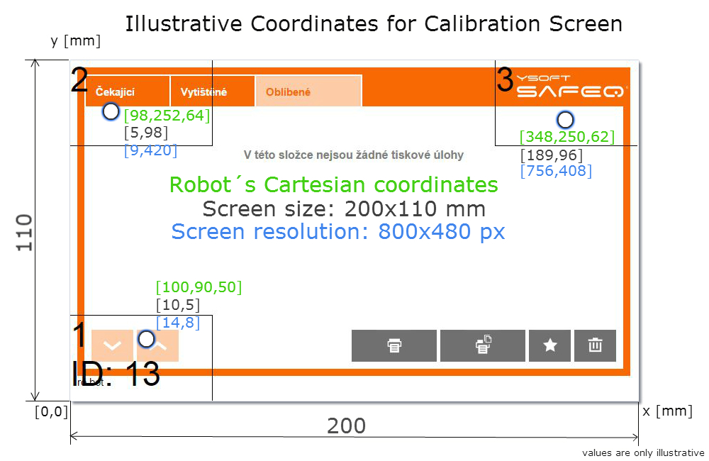
With the new semi-automatic calibration we created our custom version of Terminal server (component which handles communication with MFD) that detects any tap on the MFD screen and sends its coordinates (X,Y in pixels) into the Robot application. Screen resolution is also required so Terminal Server sends that on demand. With the knowledge of screen dimensions and screen resolution robot is able to calculate position of a tap (in pixels) to position on the screen (in millimeters) and save the end effector’s position. The semi-automatic calibration procedure is almost the same as the basic one but robot can be navigated to any point within a marked rectangle, not just the specific point at the corner. This nullifies the need for precision. However, in this case a problem occurred in form of inaccurate values of Z axis. For this purpose we have developed an automatic recalibration. This recalibration takes data gained from semi-automatic calibration and automatically repeats the procedure of semi-automatic calibration with the knowledge of existing corners of the screen. It goes through those three corners same as before, however it starts higher above each point and slowly descends to accurately measure the Z coordinate. After recalibration all data from semi-automatic are forgotten and replaced with the values from automatic calibration. This procedure eliminates any error made by an engineer during calibration and makes the robot´s calibration nearly perfect.