Reaction time measurement is a process of acquiring timespan for how long it takes for the tested device to change its state after clicking on action element. The most common scenario is the measuring of time needed to load new screen after clicking on the button that invokes screen change. This measurement directly testifies about user experience with the tested system.
So how does our robotic system do it?
The algorithm of reaction time measurement is based on calculation of pixel-wise differences between two consecutive frames. That simply subtracts values of pixels of one image from another. Let’s have two frames labeled as fr1 and fr2, there are three main types of difference computation:
- Changes in fr1 according to fr2: diff = fr1 – fr2
- Changes in fr2 according to fr1: diff = fr2 – fr1
- Changes in both directions: diff = | fr1 – fr2 |
The last mentioned computation of differences is called Absolute difference and is used in our algorithm for reaction time measurements. In general, the input frames are grayscale 8-bit images of the same size. Computation of differences for color images is possible however it would only deliver more errors in RGB color spectrum due to more variables being dependent on surrounding lighting conditions. The final computed difference is just a number indicating the amount of changes between two frames, therefore, it is perfect for detecting the change of screen in the sequence of images.
Enough of theory, let’s make it work!
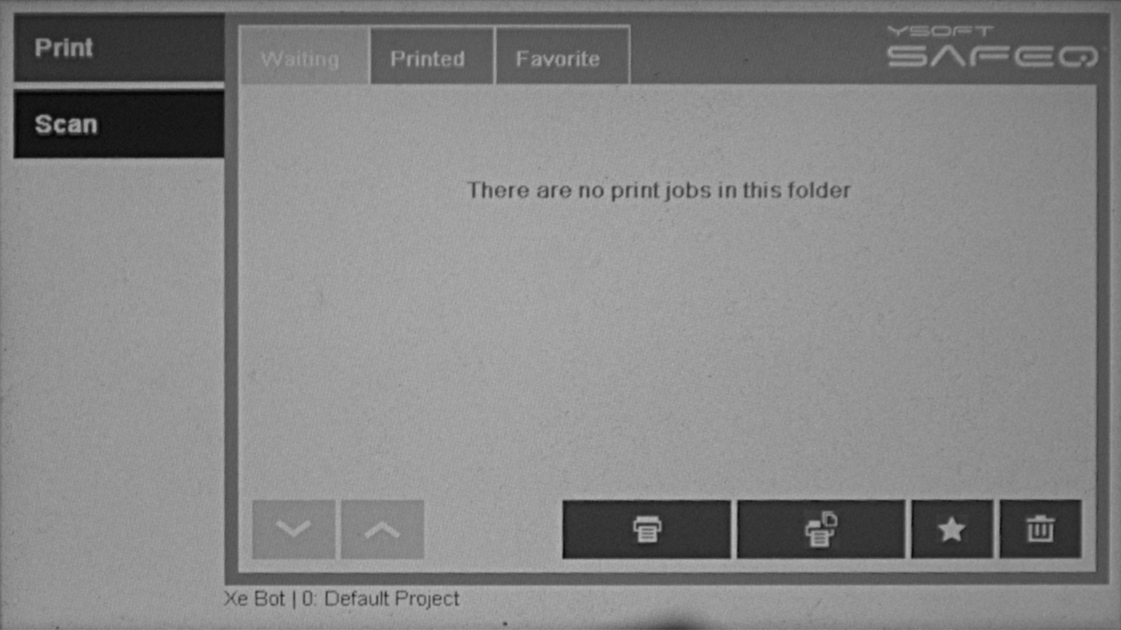
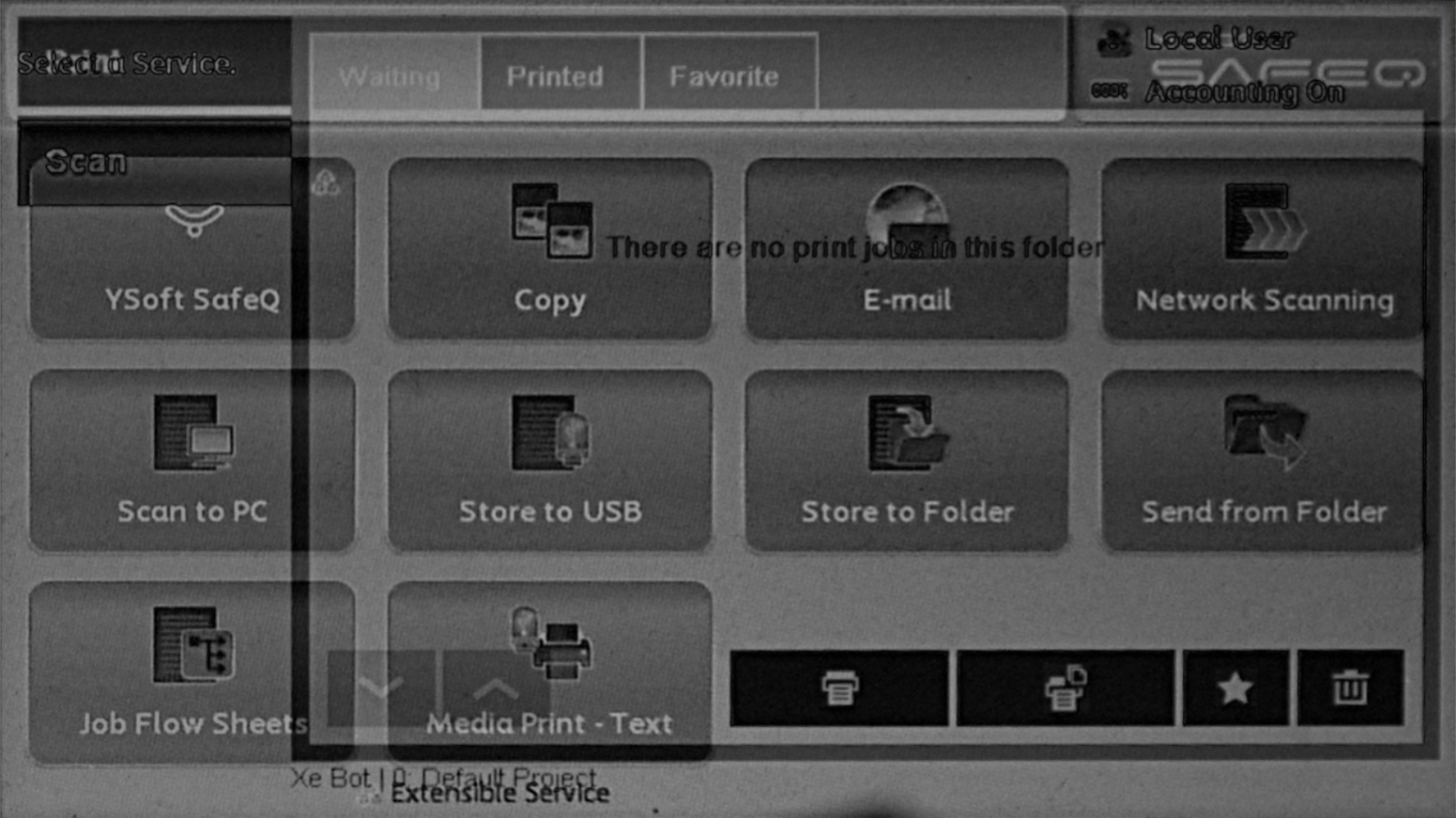
First of all, we need two images indicating the change of screen. For this purpose, I choose the following two pictures.
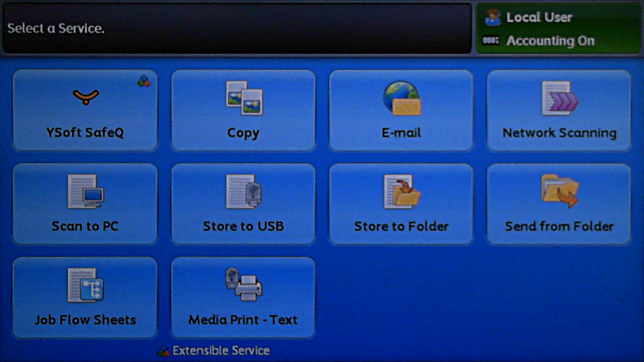
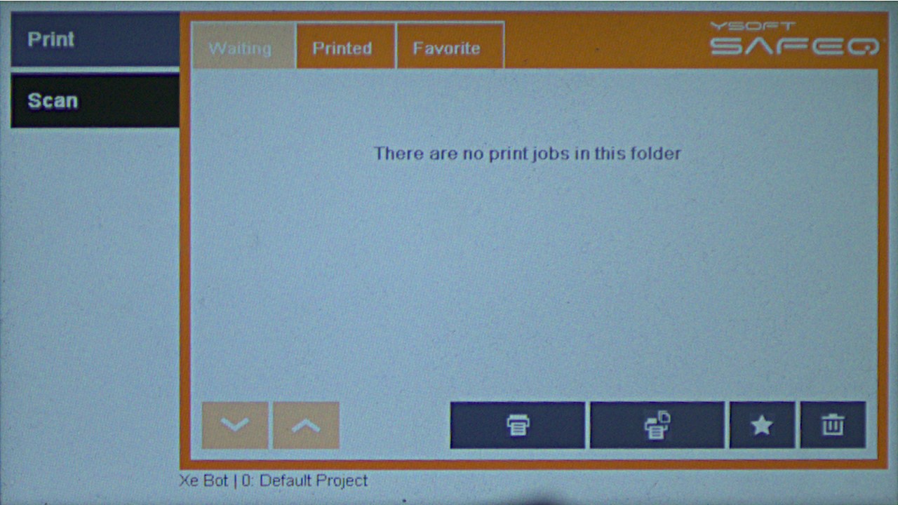
Imagine those are the two consecutive frames in the sequence of all frames we talked about earlier.
Next step is to change them into grayscale and make sure they are of the same height and width.
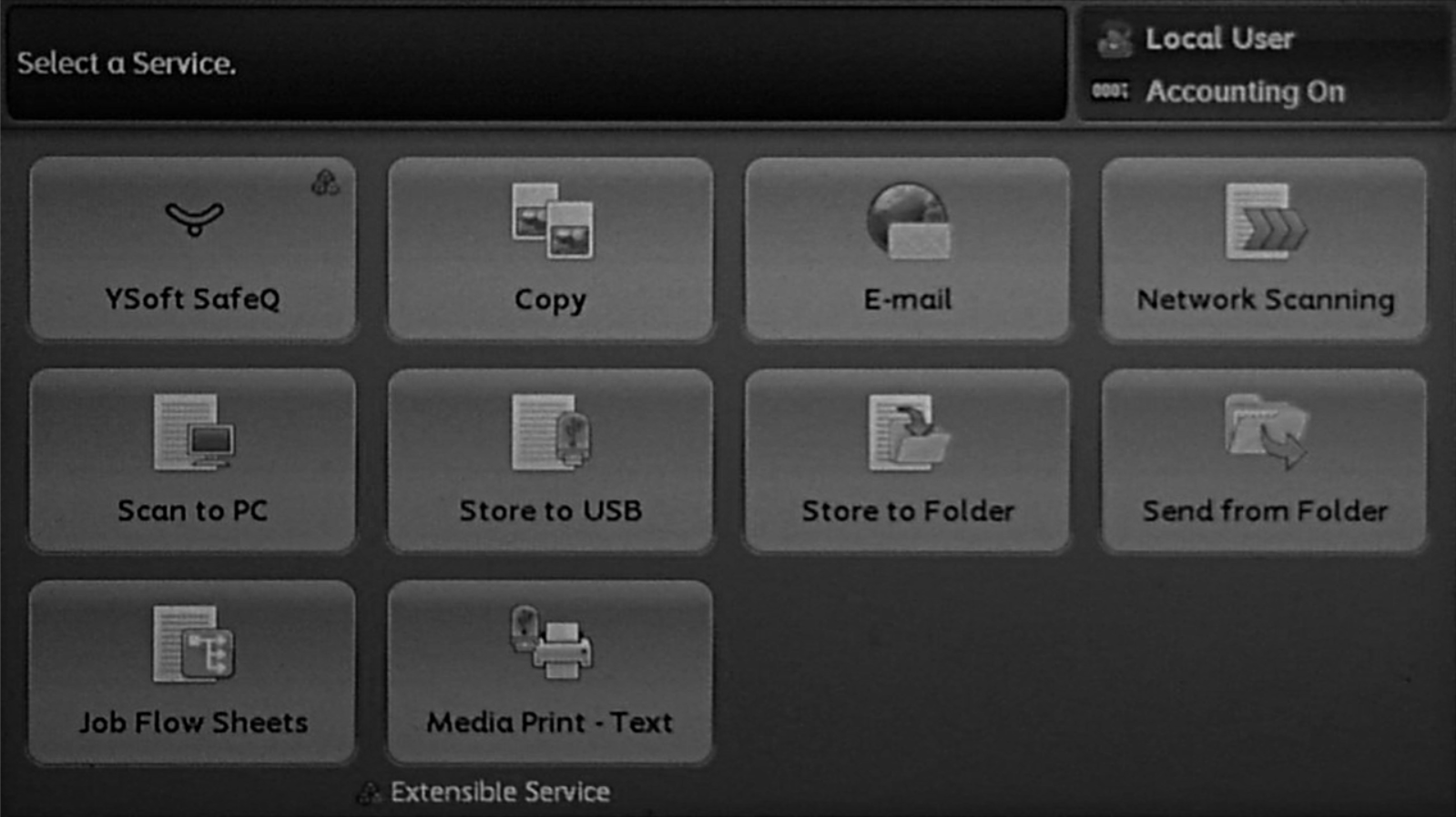
After those necessary adjustments, we are ready to calculate the difference between them. As was told before, it is computed as an absolute subtraction of one image from another. In about every computer vision library there is a method implemented for this purpose, i.e. in opencv it is called AbsDiff. The following image shows the result of subtraction of two images above. As you can see there is a visible representation of both images. That is completely fine because every non zero pixel tells us how much given pixel is distinct from the same pixel in the second image. If result image would be black it would mean that difference is zero and images are identical, vice versa for white image.
Next step is to sum values of all pixels in the result image. Remember that each pixel value for grayscale 8-bit image is in a range from 0 to 255. The difference for this image:
diff = 68964041
This value itself is not very descriptive of the change between the two images, therefore normalization needs to be applied. The form of normalization we use is to transform that computed difference number into a percentual representation of change in the screen with a defined threshold. Threshold specifies what value of a pixel is high enough to be classified as changed so rather than computing sum of all pixels in result image we find how many of pixels are above the defined threshold. The normalized difference for this image:
diffnormed =96.714% (with threshold =10)
This result compared to the previous one very precisely tells us how much change happened between the two images. The algorithm to detect the amount of change between two images was just the first part of the whole time measurement process. In our robotic system, we have implemented two modes of reaction measurement, Forward and Backward reaction time evaluation.
Forward reaction time evaluation
Forward RTE is based on real-time-ish evaluation meaning that algorithm procedurally obtains data from an image source and process them as they arrive. The algorithm does not have the ambition to find desired screen immediately but it rather searches for screen changes, evaluates them and then compares them to desired one.
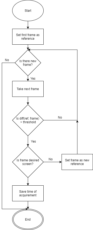
Forward RTE diagram shows the process flow of the algorithm. At the start, it sets the first frame as the reference image. Differences against this reference are then computed with incoming frames. If the computed difference is above the threshold then the frame is identified and the result is compared to desired screen. If this does not match, the frame is set as new reference and differences are then calculated against it. If that does match then timestamp of image acquirement is saved and the algorithm ends. In theory, every screen change during measuring is identified only once, however it strongly depends on the threshold value that user needs to set. Even if this algorithm tries to be real-time the identification algorithms take so much time that it is not possible yet.
Backward reaction time evaluation
Backward RTE works pretty much the other way. Rather than searching desired image from the start, it waits for all images to be acquired, identifies the last frame and sets it as a reference, after that looks for the first appearance of given reference in sequence.
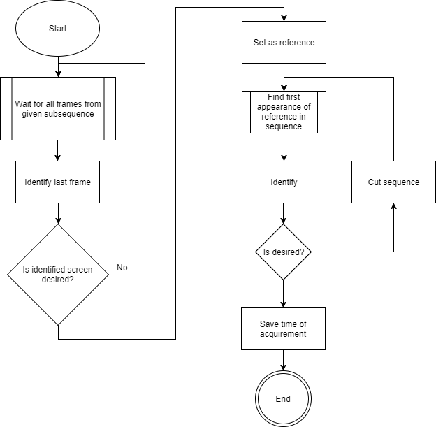
Backward RTE diagram shows the process flow of the algorithm. First of all, it waits for all frames from the subsequence of frames. After all frames are acquired, the last frame is identified and if the last frame is the actual desired screen then the reference is set and the algorithm proceeds. If the last frame was not desired screen it would mean that desired screen did not load yet or some other error happened. For this case, algorithm records backup sequences to provide additional consecutive frames. If there is no desired screen in those sequences then the algorithm is aborted.
After reference is set the actual algorithm starts. It looks for the first frame which is very similar to the reference one using difference algorithms described earlier. Found image is identified and compared to desired. If identified and desired screens match then the time of acquirement is saved and the algorithm ends. However, if they do not match then the sequence is shortened to start at the index of falsely identified frame and then the algorithm searches further. The furthest index is the actual end of sequence because image at the end sequence was at the start of RTE identified as desired.
Summary
This article contains information about difference based measurement of reaction time. It guides you through computation of differences between two images. Also, this article describes our very own two reaction time evaluation modes which we use in practice.
Additional notes
To keep the description of algorithms as readable as possible few adjustments are missing. Preprocessing of the images is the essential part where elimination of noise has high impact on the stability of the whole algorithm. We have also implemented few optimization procedures that reduce the amount of data that needs to be processed, e.i. bisection.