In the previous post, I wrote about testing requirements, which led us to create Modular sensor platform. I told you about ASP.NET Core technology, which can simplify developing web API server application. You could try developing your own API server. Today I am going to introduce you USB to CAN converter and universal board for connecting sensors.
USB to CAN converter is the STM32F4 powered device for translating USB communication to CAN bus and vice versa. The converted is USB HID class based device. The HID class was chosen because there is guaranteed delay of packets, which is an important parameter in some cases of measuring a response time of testing devices. It is connected to the web server by USB micro and there are two RJ12 connectors on the board. RJ12 connectors are used for connecting sensors or actors (see image below).
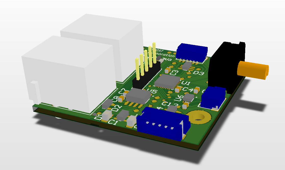
Sensors and actors
Sensors and actors can be connected to USB converter via cable with the RJ12 connector through which it is powered and it can receive and sent messages from web API server. The board on CAN bus have to be addressable by a unique address. So each device has its own encoder. Using encoder on the board, you can set the address of the device (see image below – the black box with orange shaft). The encoder is 4 bit, so you can add up to 16 different devices.
The universal version of the board has 3 connectors (the blue ones). These connectors you can use for connecting different kinds of SPI or I2C sensors. The following sensors are in process of development:
- RGB sensor – For sensing status of LED of a tested device
- Paper sensor – Detection of paper in printer
These sensors will be introduced in upcoming parts of this article series. The advantage of the universal board is that it simplifies developing new sensors. You do not have to develop custom PCB (Printed Circuit Board), but you can use this board, connect sensor and write firmware specific to the sensor
The firmware is written in pure C using STM32 HAL library (Hardware abstraction layer). The initialization code was generated by STM32CubeMX, which is a graphical software configuration tool that allows configuring MCU by graphical wizards. The tool allows configuration of pin multiplexing, clock, and other peripherals configuration. Then you can generate C project for any common embedded IDE.
Both PCBs were designed in CircuitMaker by Altium, which is free also for commercial use. There is no license to worry about. The disadvantage is that you have only two private projects, others must be public (see circuitmaker.com).
Summary
The article describes the hardware part of the Modular sensor platform. The USB to CAN converter and the universal sensor board for developing custom devices compatible with the platform. The concrete developed sensor and actors will be in next parts of the Modular sensor platform series. This post also describes tools and technologies that were used for developing converter and sensor board. If you are interested in developing embedded systems, you should definitely try STM32CubeMX and CircuitMaker.